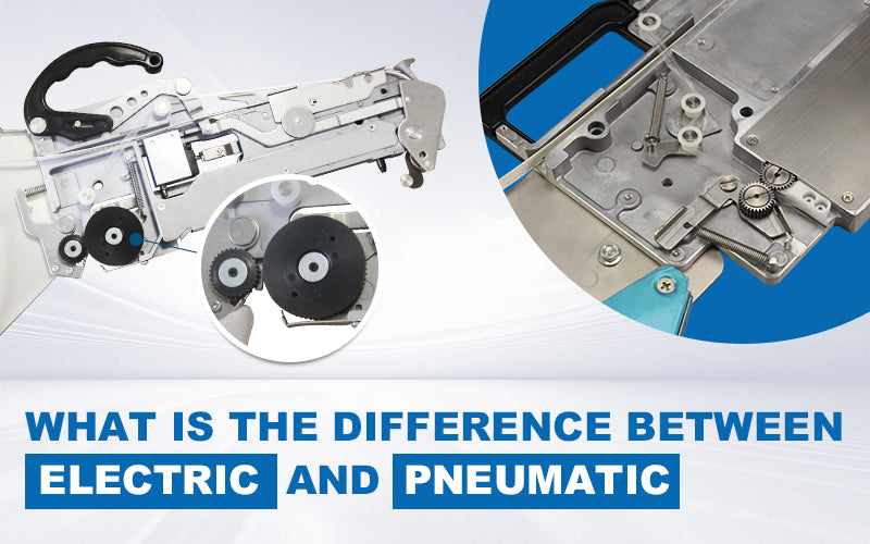


Printed Circuit Boards (PCBs) are critical components in electronic devices, providing a platform for connecting and supporting various electronic components. But many people are not familiar with the manufacturing process of circuit boards. Of course, when I first started working with PCBs, I was quite clueless as well. After a period of exploration, I came to realize that PCBs are fascinating products. They exist in various electronic devices in our daily lives, from small items like Bluetooth earphones to larger ones like TV screens. When you open up a pair of earphones, you'll see a tiny green board inside, which is what we call a circuit board. So, how is it produced? Today, let's explore!"
The process of manufacturing PCBs involves several steps:
- Cutting:
Cut the entire copper-clad board into dimensions suitable for processing from a sheet with a certain thickness and copper foil thickness.
- Drilling:
Drill conductive holes or plug holes on the board according to the computer drilling program.
- Copper Plating:
Deposit a thin layer of chemical copper in the drilled holes. The purpose is to chemically deposit a layer of copper on the non-conductive epoxy glass cloth substrate (or other substrates) to facilitate subsequent electroplating to form the circuit.

- Full Board Copper Plating:
Mainly to thicken and protect the thin layer of chemical copper to prevent oxidation in the air, forming holes without copper or breakthroughs.
- Circuit (Pattern Transfer):
Apply dry film or silk screen with graphic resist ink on the board. After exposure and development, create the circuit pattern.
- Graphic Electroplating:
Thicken the copper on the board with the pre-made circuit pattern to a certain thickness in holes and traces, allowing it to carry a certain amount of current.
- Etching:
Remove excess copper foil by stripping off the graphic resist ink or dry film, resulting in the desired conductive circuit pattern.
- Desoldering (Tin Stripping):
Remove the tin layer formed on the pattern to expose the required circuit.
- Silkscreen Solder Mask Ink or Apply Solder Mask Dry Film:
Print a layer of solder mask ink on the board or apply a layer of solder mask dry film. After exposure and development, create the solder mask pattern. The main purpose is to prevent short circuits between traces during soldering.
- Gold Plating/Tin Spraying:
Deposit gold or spray a layer of tin where soldering is needed. This facilitates soldering and prevents oxidation of the copper surface in those areas.
- Marking (Silkscreen):
Print some distinctive characters on the board, mainly for customer reference during component installation.
- Stamping/Forming:
Process the shape of the board according to customer requirements.
- Electrical Testing:
Use a closed circuit method to check for open or short circuits in the PCB.
PCB production is a challenging and complex process that involves many steps. Each step needs to be carefully executed, as any deviation may lead to the scrapping of the PCBs. Therefore, it requires skilled personnel and precise technical control in the factory.
If you would like to know more, pls check the videos,