


What is the SMEMA?
SMEMA, or the Surface Mount Equipment Manufacturers Association, is an industry-standard interface protocol that ensures the compatibility and interconnectivity of various machines and equipment used in surface mount assembly lines. Its primary purpose is to facilitate the exchange of essential information and signals between different machines, enabling a seamless, integrated manufacturing process.
Application
SMEMA is widely used in electronics manufacturing for various applications, including:
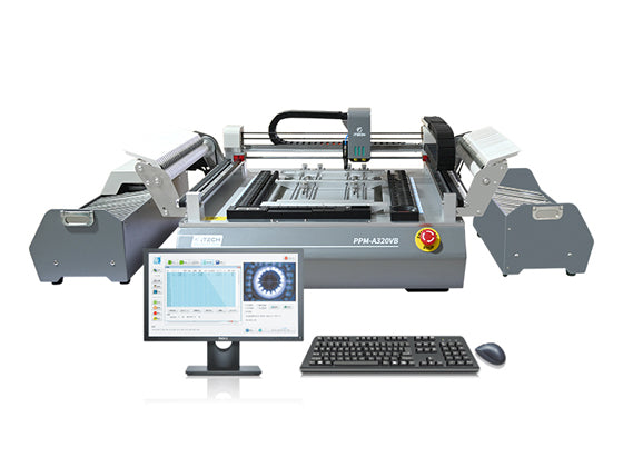
SMT Pick and Place Machines: SMEMA allows pick-and-place machines to communicate seamlessly with other equipment in the assembly line, such as soldering machines and conveyors.

Conveyors: It helps control the speed and direction of conveyor systems, ensuring synchronized movement of PCBs between different workstations.

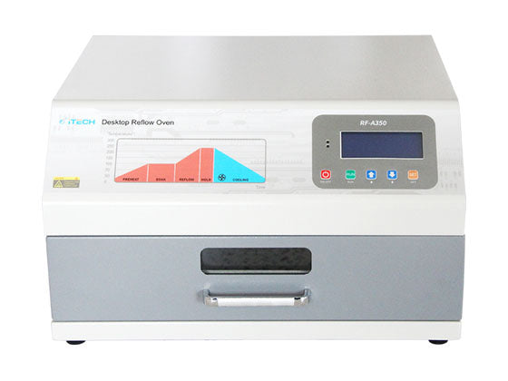
Soldering Equipment: SMEMA helps control and monitor the soldering process, ensuring temperature profiles and cycle times are accurately maintained.
Inspection and Testing Machines: This standard enables data exchange between inspection and testing equipment for quality control and process optimization.
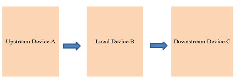
Equipment Diagram
How SMEMA Works?
SMEMA functions as a communication protocol, allowing machines to send and receive signals through a standardized interface.
Logical relationship of SMEMA interface standard
- When the equipment has a board (the discharging sensor has a signal or the program step determines that there is a board to be transmitted downstream), the "board signal" is output (that is, the contact is closed)
- When the equipment requires a board (the program step requires board entry), the "board required signal" is output (that is, the contact is closed)
- When the upstream device A has a board and the local device B wants a board, and the two contacts are closed at the same time, and the continuous time exceeds 50ms (to prevent signal jitter), the upstream device A starts to send the board to the local device B.
- Upstream equipment A delivers the board. When the board leaves the equipment (leaving the discharging sensor or belt action distance or delaying judgment to meet the conditions), the "board signal" contact of upstream equipment A is disconnected.
- The upstream device A sends the board, and when the local device B receives the board (the input sensor meets the conditions), the "board signal" contact of the local device B is disconnected.
- The device does not start sending boards at least 50ms after each signal is generated.
- Upstream equipment A sends the board. If the board cannot leave upstream equipment A within the specified time, an error message will be generated.
- When upstream device A sends a board, if local device B cannot receive the board within the specified time, an error message will be generated.
- The local device B sends boards to the downstream device C. The same applies.
Hardware Requirements of this Standard
For equipment to be SMEMA-compliant, it must meet certain hardware requirements. This includes having appropriate connectors and sensors to send and receive signals. These connectors should be standardized to ensure compatibility between different equipment types and brands. Moreover, equipment should feature the necessary input and output channels, which allow for the seamless exchange of signals and data with other machines in the assembly line.
Signal Transmission Methods
SMEMA uses both digital and analog signals for communication. Digital signals often include binary on/off signals, whereas analog signals can convey information such as board speed or direction. These signals are transmitted through the standardized connectors and wiring.
- When upstream device A transmits to local device B
When upstream equipment A completes processing and is waiting to be sent out - pins SMEMA 3 and 4 of its upstream equipment A end are connected (with board), making the input port of the controller B of the local equipment effective.
When the local equipment B has completed processing and is waiting for the board to be loaded - the pins SMEMA1 and 2 of the local equipment B are connected (requiring boards).
When the local device B is waiting to enter the board, it should output the board requesting signal (inlet SMEMA1 and 2 pins are connected). If it is detected at the same time that the board of upstream device A to be ejected (pin SMEMA3, pin 4) is connected for 50ms (filter time), the device should perform "pre-board" transmission until the incoming board transmission takes effect. If during this process, "upstream device A "When the ready output disappears, the pre-advance board disappears and the device does not alarm.
When the device B of this machine sends out a plate requesting signal, (regardless of whether it is in the process of pre-feeding the plate), the product is sensed at the feed port (it can be delayed appropriately). Trigger the advance plate transport and disable the pre-advance plate at the same time.
- When local device B transmits to downstream device C
When the local equipment B is processed and waiting to be sent out - SMEMA 3 and 4 pins at its outlet end are connected (with boards), making the input port of the controller of the downstream equipment C effective.
When the downstream device C sends a board request signal - the SMEMA1 and 2 pins of the B terminal of its local device are connected (there is a board). The input port of controller B of this machine is valid.
When the downstream device C is waiting to enter the board, it should output the board requesting signal (inlet SMEMA1 and 2 pins are connected). If it is detected at the same time that the local device has a board signal (SMEMA3, pin 4) connected for 50ms (filter time), the device should perform "pre-board" transmission until the board transmission takes effect. If during this process, the "local device B" ready output disappears, then the pre-advance board disappears and the device does not alarm.
When the downstream equipment C sends a plate requesting signal, the product is sensed at the feed port (regardless of whether it is in the process of pre-feeding the plate) (it can be delayed appropriately). Trigger the advance plate transport and disable the pre-advance plate at the same time.
- Reserved functions
In order to prevent the docking of non-SMEMA protocol equipment, the equipment should reserve the next station signal compensation function, so that the equipment can also complete the board release under non-SMEMA conditions.
When the product disappears without being shipped out of the board, detection should be started. When a product cannot be detected, an alarm will be output based on the device structure, or the product information will be cleared, and manual removal will be the default.
SMEMA plays a pivotal role in the world of electronics manufacturing by providing a standardized interface that enhances the efficiency and coordination of surface mount assembly lines. This protocol enables machines to seamlessly communicate, resulting in optimized processes, reduced errors, and increased productivity, making it an indispensable standard in today's electronics manufacturing industry.